Setup a Beautiful Dashboard to Monitor Temperature and Battery Voltage. [Idea]

Recently I want to install a Temperature Insulation in my house since it’s very hot in daylight. But I really curious if this insulation really work lowering temperature in my house? For this obviously I will need a temperature sensor. So There is DHT-11 a very low price and low resolution with high noise level which I don’t know. So I start connecting this DHT-11 to Node-MCU.

The goal is I want to connect this Node-MCU via Wi-Fi and transmitting the temperature data using MQTT protocol. But first, I need to look how I can do that! It’s easy just use arduino programming and some example while I ever create a button IoT to turn on a LED. So this must be not hard right? Well If I only want to probe single value then it’s done!

The problem is, I want to compare the temperature data before the Insulation installed and after the insulation installed, so I will also need a data storage. Storing data is easy if it’s just for storing. But we want to easy access for it. This remind me how data visualization really helping in making decision and create an insight for the collected data. This remind when benchmarking a video conference platform a while ago using kubernetes, docker, and more importantly a Grafana! My client and my friend saying this tools really help us understand what went wrong with their video conference. I will write it later when I have more time (and off course permission). So yeah I want to use Grafana again for my personal project. So there is my final goal. It’s time to set the course for!

Now, I have Node-MCU and DHT-11 as my sensor node with MQTT as transport protocol. I also have deploy Grafana with InfluxDB in my previous work. All we need now is how we can bridge this two? So instead of re-inventing the wheel why not googling and see if any other people has done it and publish a “how to”. After a while googling with couple keyword I found one person who really done it in a way that really suit my need and preferences. He really good and he also use docker to deploy the idea which really make everything more scalable, moveable and replicable. I owe a lot to him. You can find the idea from here: http://nilhcem.com/iot/home-monitoring-with-mqtt-influxdb-grafana

After reading a while how he implement the idea, I can see that he using a python to bridge between MQTT and InfluxDB. So, it’s time to implement the thing. I start from installing a broker, subscriber, and publisher in raspberry so when the Node-MCU already publishing some data I can see if it’s work correctly or not. Here’s what I do to install:

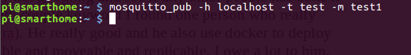
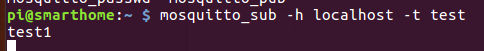
$ sudo apt install mosquitto mosquitto-clients

And here’s what I do to check if the broker already up and ready to “brokering”, first I open two terminal (ssh) to my rpi. One for subscriber:

$ mosquitto_sub -h localhost -t test

and other terminal for publisher:

$ mosquitto_pub -h localhost -t test -m test1

If everything done correctly I should get the message “test1” in my subscriber terminal. So. Yes I have it! Time to start the Node-MCU and check if the topic published from Node-MCU get into rpi.

I think this is for our first part. I will continue with how the bridge and docker setup in the next part.

How much battery you need for your (off grid) house?

To know how much battery you actually need to know how much you use per day. For most of us perhaps we don’t really know how much energy we use per day. The good news is you can estimate from you monthly electricity billing and how much every KWh cost.

For example in my country every KWh cost around Rp 1.500,00. Let’s say Rp 1.400,00 every KWh so we can get higher number for safety. Then we can divide monthly electricity billing, for example: Rp 500.000,00 with how much every KWh cost: Rp 1.400,00.


monthlyEnergyUsage = \frac{monthlyBilling}{costEveryKWh}
357,14 = \frac{500.000}{1.400}

It’s 357,14 KWh every month. Then we can divide this number by 30 to get energy usage per day.

11,904 = \frac{357,14}{30}

From our calculation in average energy used are 11,904 let’s round it up to 12 KWh for safety. Here we get our energy usage daily. Now you know you need battery which can hold energy this much. But wait, I don’t know which battery I need and how much battery is holding 12 KWh. OK, let’s assume we are going to use Lead Acid battery. The next section we will talk about Lead Acid battery and some specification we need to know.

What is Lead Acid battery?
It’s one we use in our car to mainly start our car. Actually it’s only one variant of Lead Acid battery. LA battery come in many variant and every variant has it’s own Depth of Discharge (DoD) and

For most LA battery can only discharged to 60%. It’s means we can only get 40% out of energy stored in our battery. This means our DoD is 40%. For example we have 12V 100Ah LA Battery, means it’s nominal voltage are 12 Volt and it’s capacity is 100 Ampere Hour.

What is 100 Ampere Hour? This means if we drain this battery in 100 Amp This battery will supply as long as 1 Hour, If we drain this battery in 50 Amp this battery will supply as long as 2 Hour. Well you got it right? But wait, this battery is LA battery, which mean s we only should drain it 40% of it’s stored energy only. Which means if we drain in 100Amp we only should drain it as long as 24 minutes. OK enough talking about Ah and DoD, we still don’t tell how much KWh this battery hold? it’s easy to calculate it:

capacityInKWh = nominalVoltage \times Ah \div 1000
1,2 = 12 \times 100 \div 1000

Here we get that our battery capacity is 1,2 KWh. But don’t forget about DoD we talk earlier LA battery is 40%. which means this battery only has useful capacity 0,48 = 1,2 \div 0,4 yes 0,48 KWh. Now take the number 12 KWh for our daily usage it’s easier to know how much we need battery right? it’s

25 = 12 \div 0,48

Yes at least we need 25 batteries for one day operation. FYI it’s unsafe to only have one day worth of energy it’s safer to have at least two and a half day worth of energy for safety. So yes, you will need about 63 batteries.

There is comment section to CMIIW. Also any input are welcome.

WISP mode in Open-WRT

In Open-WRT you can configure your router as a “Range Extender”. Not exactly as “Range Extender” because you will create different SSID.

This post is a sequel from my post here. I will using TP-Link Router which I (finally) manage to flash with Open-WRT. This router are fresh from flashing, which means, everything is default and it has no password yet. I prefer to set the password later as it will help us to configure quickly.

This is Step-by-step
A. Initial Step: Connecting to Router
1. First you will need to connect the router with your computer using LAN Cable.
2. After your computer get IP through DHCP from router, go to 192.168.1.1 to your router with your internet browser (I am using Chromium).
3. You will prompt to set the password, please do that later. Instead just click login.

B. Changing router IP from 192.168.2.1 to 192.168.2.1

4. First of all you need to change the router IP to 192.168.2.1 If you don’t need it skip this step and go to section C. I require doing this because the Hot Spot I will connect using the same IP address. Doing this will also changing DHCP configuration.
4.1 go to Network -> Interfaces

4.2 on LAN click Edit

5. change the IP Router from 192.168.1.1 to 192.168.2.1, by changing field IPv4 address to click “save”

You need to do next step in under 30 second after you click “save and apply”
6. disconnect your PC connection immediately and reconnect so you will get new IP address from 192.168.1.xxx to 192.168.2.xxx.
7. from your browser go to 192.168.2.1
Fail to do so in 30 seconds will revert back the configuration you already set.

C. Connecting to the wireless you want
8. Go to Network –> Wireless
9. on Wireless Overview click Scan

10. click Join Network on SSID you have access

11. After success joining a wireless the router will also create another router as a master

Flashing TP-Link TL-WR840N v4 with Open-WRT using FTP method

TP-Link TL-WR840N are made by TP-Link with lot of version. This tutorial specify to version 4 (v4) which has MediaTek MT7628AN chip with 8 MB Flash and 64 MB RAM. It’s quiet huge for the price, and most importantly it support Open-WRT and (hopefully) will supported for the next version of Open-WRT. In Indonesia, my country, I can get this second hand pretty cheap from local online marketplace.

My router looks very similar with this picture.

For detailed information about openwrt and flashing you can see here. At first attempt flashing, I don’t get lucky and made a mistake by downloading the wrong image. This mistake set me back about 4 to 6 hours. The symptom which I get when flashing with wrong image is the LED looks like the router are running on bootloop.

At first I thought this bootloop LED looks like it’s flashing, since this is my first time flashing Open-WRT to TP-Link router I don’t know which pattern is flashing and which is booting. Then after so long “flashing”, I start to curious and decide to open the casing and attach serial monitor, then it tells me that extracting the linux are failed. I don’t know what’s wrong and try to download the original firmware from TP-Link webpage. after trying to flashing with FTP method, the error remain the same although the file clearly different.

Warning, flashing your router with 3rd party image can result bricking your route, or broke it. I already told you on the earlier paragraph. Please do at your own risk!

It also will void your warranty, if any.

After reading correctly from openwrt webpage, finally I manage to download the right image and flash it. Voila, it’s work in just couple of minute. How fool me. So if you want to read a thorough step-by-step how to flash the router with Open-WRT go here. (sorry it’s still being written, please read below for a while, or ask in comment in which part you are stuck)

In summary, it’s consist of X thing, if you are geek enough you can go to the source which I give you the link too, at every step:
1. Setup TFTP on your linux box (here)
2. Download the image and put the image at TFTP directory (here), please download at the column “Firmware OpenWRT Upgrade”. It’s clearly tell you if you are using tftp method. Don’t repeat my mistake. (you have been warn)
3. Copy and rename the image to TFTP directory.
4. Set the computer IP to static 192.168.0.66
5. connect the LAN Cable while the router is off
6. Push and hold the (only) button while connecting the router to the power supply, count 1 to 10 and release.
7. Hopefully everything goes right and the power LED will flash very rapidly, and only the power LED. The other LED won’t turn on until the flashing is done.

After reading the openwrt web page a little more thorough this time, I also try to restore the Official TP-Link Firmware which I download earlier, and manage to success. Yes the key is reading thoroughly, (almost) everything is already written at openwrt web page.

What can you do with TP-Link flashed with Open-WRT? a lot! In the next tutorial I will write how you can use the router as Wi-Fi range extender and create your own SSID.

Configuring Wireless in Buildroot [buildroot part-5]

In previous post we already cover about how we can Enable the Wi-Fi. Until then, we still unable to use them in our linux. In this part, we shall cover how to configure and connect to Wi-Fi hotspot using some tools we will enable and configure these tools using configuration file.

Here we go:

$ make menuconfig

  1. Enable wireless tools, dhcpcd and dropbear
    networking application:
  • Target packages
  • – Networking applications
    [] dhcpcd [] dropbear
    [*] wireless tools
  1. Enable libpjsip
  • Target packages
  • – Libraries
  • – – Networking
  • – – – [*] libpjsip
  1. create password for root user (important to access via ssh):
    System configuration —>
    () Root password

To configure wireless we will use and configure wpa_supplicant we will use rootfs overlay which we already setup at the post before:

Editing wpa_supplicant.conf:

$ wpa_passphrase SSID pass
network={
ssid=”SSID”
#psk=”PASSword”
psk=9d62b9cb3ca9f032bffd7257f8453acfcee2d91d600501a05f491fcc04a8d075
}
add the configuration above to /etc/wpa_supplicant.conf at our target rootfs:

$ mkdir board/tryingrootfs/beagleboneblack/rootfs-overlay/etc/
$ vi board/tryingrootfs/beagleboneblack/rootfs-overlay/etc/wpa_supplicant.conf

[i]

network={
ssid=”SSID”
#psk=”PASSword”
psk=9d62b9cb3ca9f032bffd7257f8453acfcee2d91d600501a05f491fcc04a8d075
}

[esc]

[:wq]

$ mkdir -p board/tryingrootfs/beagleboneblack/rootfs-overlay/etc/init.d
$ vi board/tryingrootfs/beagleboneblack/rootfs-overlay/etc/init.d/S99wlan

[i]

!/bin/sh

echo Starting WLAN
/usr/bin/wlan_up &

[:wq]

change the mode of the file so it’s executable:
$ chmod +x board/tryingrootfs/beagleboneblack/rootfs-overlay/etc/init.d/S99wlan

$ mkdir -p board/tryingrootfs/beagleboneblack/rootfs-overlay/usr/bin
$ vi board/tryingrootfs/beagleboneblack/rootfs-overlay/usr/bin/wlan_up

[i]

!/bin/sh

until iwconfig | grep wlan0; do sleep 5; echo ” tick “; done
ifconfig wlan0 up
wpa_supplicant -iwlan0 -c /etc/wpa_supplicant.conf -Dwext -B dhclient
udhcpc -i wlan0

[:wq]
$ chmod +x board/tryingrootfs/beagleboneblack/rootfs-overlay/usr/bin/wlan_up

Create our image:
$ make
Then write the image to micro sd-card and test if our beaglebone can connect to the Wi-Fi we describe in wpa_supplicant.conf.

Using rootfs overlay in buildroot [buildroot part-4]

If we wanted buildroot to automatically copy some file in root file system in our target, we can use feature called “rootfs overlay”. This feature of buildroot enable us automate copying some file into root file system, usually it’s a configuration file.

$ make menuconfig

  • System configuration
  • – () Root filesystem overlay
    we should fill this option with this:
    board/tryingrootfs/beagleboneblack/rootfs-overlay/
    so it will look like here after we edit it:
    (board/tryingrootfs/beagleboneblack/rootfs-overlay/) Root filesystem overlay

Off course then, we should try it right?
To try it, we should make the directory in our buildroot in our root buildroot
Note: from now on if there’s mentioned “root buildroot” means directory buildroot-2018.02.04/. got it?
$ mkdir -p board/tryingrootfs/beagleboneblack/rootfs-overlay
then let’s demonstrate what this means then? let’s make a new file
$ mkdir -p board/tryingrootfs/beagleboneblack/rootfs-overlay/root
$ touch board/tryingrootfs/beagleboneblack/rootfs-overlay/root/testRootFSOverlay

exit menuconfig and make:
$ make
Now, every file we put in overlay directory will automatically copied to our root file system image. This could make automating configuration file easier and faster.

Enabling Wi-Fi USB Dongle in buildroot [buildroot part-3]

In this post we will talk about how to enable two kind chipset of Wi-Fi USB dongle in buildroot.

1. Atheros in TP-Link 722

We will start from kernel configuration:
$ make linux-menuconfig

1 cfg80211

  • Networking support
  • – Wireless
  • – – [*] cfg80211 wireless extensions compatibility
  • – – <*> Generic IEEE 802.11 Networking Stack (mac80211)

2 atheros wireless

  • Device Drivers
  • – Network device support
  • – – <*> USB Network Adapters —>
  • – – [*] Wireless LAN
  • – – – [*] Atheros Wireless Card
  • – – – – <*> Atheros HTC based wireless cards support
  • – – – – <*> Linux Community AR9170 802.11n USB support
    exit the linux-menuconfig

Then we will continue to buildroot configuration. In this section we will enable the firmware for Atheros:
$ make menuconfig
3 USB Wi-Fi Atheros firmware:

  • Target Packages
  • – Hardware Handling
  • – Firmware
  • – – – [*]linux – firmware
  • – – – – [*]WiFi firmware
  • – – – – – [*] Atheros 9170
  • – – – – – [*] Atheros 9271

Exit the menuconfig and Create our image:
$ make
Then write the image to micro sd-card and test if our beaglebone can identify Atheros Wi-Fi USB Card

note:
TP-Link still produce this model, unfortunately the chipset is difference in latest version. It’s not Atheros anymore. So this tutorial aren’t compatible with such dongle.

2. Realtek RTL8188EUS in TP-Link

In this section we start by configuring the builldroot:
$ make menuconfig

  • Target Packages
  • – Hardware Handling
  • – [*] rtl8188eu

Exit the menuconfig.

Next we need to enable driver in kernel configuration:|
$ make linux-menuconfig

  • Device Drivers
  • – Network device support (NETDEVICES [=y])
  • – – Wireless LAN (WLAN [=y])
  • – – – <*> Realtek rtlwifi family of devices
  • – – – <*> RTL8723AU/RTL8188[CR]U/RTL819[12]CU (mac80211) support
  • – – – – <*> Realtek RTL8192CU/RTL8188CU USB Wireless Network Adapter
  • Device Drivers
  • – [*]Staging drivers
  • – – <*> Realtek RTL8188EU Wireless LAN NIC driver
    exit linux-menuconfig
    Create our image:
    $ make
    Then write the image to micro sd-card and test if our beaglebone can identify Realtek Wi-Fi USB Card

This chipset available in other brand of USB dongle and may valid if the chipset is same.

To use WiFi USB dongle, you need to enable the USB first. if you haven’t enable the USB, you won’t be able to use the Wi-Fi. I cover how to enable the USB in previous post here.

Next post I will cover how to configure the network and what package (application) to enable so we can configure the network easily. Hope you get some help and knowledge from this writing. Cheers.

Feedback and Correction is appreciated
See You.

Writing image in sd-card and connecting to serial terminal in BBB [buildroot part-2]

Writing image to sd-card:
For convenience i create a shell script:
$ vi writesd.sh

#!/usr/bin
sudo dd if=output/images/sdcard.img of=/dev/mmcblk0 conv=fsync

You need to verify the of=/dev/mmcblk0 to match the sd card in your computer, since running dd will erase the of=/dev/mmcblk0 disk completely. After that change writesd.sh permission to enable it to execute:
$ chmod +x

After we write the shell script, we then can call it every time we need to burn the image to sd-card:
$ ./writesd.sh

Connecting Serial Terminal to BBB:
We will need the USB-Serial with TTL level like picture below:

DO NOT use USB-Serial like the picture below:

The above USB Serial have RS-232 level which can broke your BBB Board.

and connect the USB-Serial with the BBB Board according to this pinout:

Remember to connect in Tx-Rx connection

Run the serial terminal in your linux, in this case I use picocom:
$ picocom /dev/ttyUSB -b 115200

If you need sudo, it means your user isn’t included in dialout group (in debian distro.)

Booting the BBB from sdcard:
Before we plug the power supply we need to insert the sd card we already write the image to, into BBB. In some revision BBB we need to press “the button” near the sd-card before pluging the power supply so BBB can boot from sd-card instead internal MMC. Remember to use 5V ONLY for power supply.
Wait for it to get ready to login, the user name is root without password. Then you shall see at your terminal that you can type just like in usual linux terminal.

Feedback and correction is appreciated
See You.

Introduction to Buildroot and enabling USB in BeagleBone Black (BBB) [buildroot part-1]

Buildroot is a build system made by bootlin, formerly known as free electron. With buildroot you can build a minimized linux from source and choose which package and service is running in depth and detail.

Edit 25 May 2019: to correcting workflow. Initially we configuring kernel first then buildroot. Apparently it’s better to configure the buildroot first.

Preparation:
In this tutorial we will use this Hardware:

  1. Beaglebone black (also known as BBB)
  2. USB-Serial to connect into serial terminal in BBB using your computer
  3. USB soundcard ( we will try to enable USB driver in buildroot and USB SoundCard driver, so we shall be able to record and play some sound. We also can play some music in *.wav and *.mp3
  4. Speaker and Microphone, it’s obvious that we shall need them to record and play some sound.

Software we will need:

  1. We run Operating System Linux, preferable Ubuntu, I using the 16.04 lts version
  2. buildroot-2018.02.4 you can download this in tarball from bootlin
  3. Look for dependencies needed by buildroot. you can search this dependencies at buildroot manual [link will be here soon]

Let’s get started!

Extract buildroot-2018.02.4.tar.gz at /home/user/ (or any directory you prefer and it should be where your user can read and write also it’s better if your user own the directory. You don’t need and it’s advised to NOT use root user.:
$ tar -xzf buildroot-2018.02.4.tar.gz

When we extract we will have new directory containing the extraction from buildroot-2018.02.4.tar.gz. This directory if you ain’t rename is buildroot-2018.02.4. Let’s go into this directory:
$ cd buildroot-2018.02.4

  1. Preparing the minimum system using available defconfigs

To see every available defconfigs we can call:
$ make list-defconfigs

There every available defconfig will displayed, Yes it’s a lot. let’s filter the defconfig for beaglebone board using grep:
$ make list-defconfigs |grep beagle

there you’ll shall see that for BBB there’s a defconfig for beaglebone. Let’s use it:
$ make beaglebone_defconfig

Now, every configuration is done! if we don’t need much. But, as I promise you, we will activate the USB driver and USB Soundcard driver. For this tutorial is very specific for BBB Board and the Linux kernel version I am using is downloaded from TI with version 4.4.40. I have check using kernel 4.9.xx and there is some slight difference to configure regarding the dependencies.

Configuring the buildroot
In buildroot, to configure the kernel configuration we do make linux-menuconfig, unlike if we directly configure the kernel configuration file we do make menuconfig. In buildroot, if we do make menuconfig, we will configure the buildroot configuration which configure higher layer things like toolchain, rootfs, busybox, bootloader like U-boot and some summary configuration for kernel, also to configure which package will be included. In next section we will configure toolchain and package to include:

$ make menuconfig

Enable Toolchain C++ and wchar:
– Toolchain
– – [*] Enable WCHAR support
– – [*] Enable C++ support

If we edit any toolchain configuration, we will need to run make-clean IF, we ever run make before editing any toolchain configuration. Anyway this toolchain configuration are needed by package alsamixer which we will enable in a minute

If we need to do make clean in buildroot, the kernel configuration will also be erased, so you shall back up the configuration file located in output/linux-<git-hash-number>/.config then you need to restore this .config to it’s former directory before running make. We will cover how to configure backing up and restoring this configuration file in the next part.

Enable alsa-lib:
– Target packages
– – Libraries
– – – Audio / Sound
– – – – [*] alsa-lib

Enable alsamixer
– Target packages
– – – Audio and video applications
– – – – [*] alsa-utils
– – – – – [*]alsamixer

Enable aplay/arecord
– Target packages
– – – Audio and video applications
– – – – [*]alsa-utils
– – – – – [*] aplay/arecord

Enable mpg123
– Target packages
– – – Audio and video applications
– – – – [*] mpg123

exit the menuconfig

The package we enable in menuconfig like alsa will makes it’s easier for us to use an USB sound card. aplay/arecord package and mpg123 package is a wav and mp3 player respectively so we can play some music when the image is running in BBB Board

Configuring the Kernel
As usual, to configure the linux kernel in buildroot we do this command:
$ make linux-menuconfig

First, we shall need to Enable USB:
– Device Drivers
– – USB Support – – – >
– – – <*> Support for Host-side USB

Next we need to enable Root Hub Transaction Translator (EHCI, OHCI, INVENTRA)
– Device Drivers
– – USB support (USB-
– – – <*> Support for Host-side USB
– – – <*> EHCI HCD (USB 2.0) support
– – – [*] Root Hub Transaction Translator
– – – <*> EHCI support for OMAP3 and later chips
– – – <*> OHCI HCD (USB 1.1) support
– – – <*> OHCI support for OMAP3 and later chips
— – <*> INVENTRA Highspeed Dual Role Controller (TI, ADI, AW, …)
– – – <*> TI DSPS platforms

For kernel 4.9 you’ll need to enable USB Gadget and omap (which it automatically done in 4.4.40 kernel configuration.

The sound card:


From here, we already done configuring the kernel for enabling USB with our BBB Board. Next, we will configuring USB Sound Card Driver:
– Device Drivers
– – <*> Sound Card Support —>
– – – <*> Advanced Linux Sound Architecture —>
– – – – [*] USB sound devices — >
– – – – – <*> USB Audio/MIDI driver

Exit the linux-menuconfig.

Create our image:
$ make
We will find the sdcard image in output/image/sdcard.img

If you see something like “Mass storage” while Enabling USB in kernel configuration, That is a driver for Mass Storage like USB Flash Disk or USB Hard Drive. BTW, I already done this maybe I’ll edit this tutorial later. to include mass storage driver in comprehensive.

This is it for part-1, see you in the next part which I will cover for how we can burn the image in SD-card and connect to serial terminal in BBB from our computer.

Feedback and correction is appreciated
See You.

How MPPT in Solar Charge Controller can charge a battery?

This post is a part 2 of my discussion about MPPT and solar charge controller with my Friend (SekteCinta). On part 1 we discuss about what is MPPT and why it’s exist but haven’t discuss about MPPT in battery charge controller.

SC: I still confuse about battery charger and MPPT

M: So, There is no direct connection between Battery charging voltage with MPPT.

SC: So, the relation between battery charge and MPPT is what confusing me. Here’s the quotation got from here:
MPPT or Maximum Power Point Tracking is algorithm that included in charge controllers used for extracting maximum available power from PV module under certain conditions. The voltage at which PV module can produce maximum power is called ‘maximum power point’ (or peak power voltage).

M: There is a battery charger beside an MPPT in charge controller. So you can imagine there is two block inside a charge controller,
1. MPPT
2. Charger Battery

SC:”The major principle of MPPT is to extract the maximum available power from PV module by making them operate at the most efficient voltage (maximum power point). That is to say:
MPPT checks output of PV module, compares it to battery voltage then fixes what is the best power that PV module can produce to charge the battery and converts it to the best voltage to get maximum current into battery. It can also supply power to a DC load, which is connected directly to the battery.

From the quotation, I bolted the sentence which confuse me. Can you explain this?

M: Haaa. If you already understand MPPT, then there is another thing about MPPT we haven’t discuss and need to understand.

SC: OK OK, I already understand about MPPT.

M: Because now we can “control” PV power output by variating the PWM in Transistor

SC: And?

M: As a lot people already know electricity is consumed immediately after it’s produce. While we know the problem with electric storage (in this case battery) is it’s power storage rate are limited. So if the output produced by MPPT can’t consumed or absorb by the battery, why should MPPT acquired maximum power from the PV right?

SC: What? I still don’t understand………

M: Oooops, Please elaborate which part you haven’t understand?

SC: So if the power output produced by MPPT can’t stored by battery, why should MPPT acquire maximum power from PV right?

M: Yes!

SC: Isn’t MPPT always used or MPPT algorithm always running right?

M: Well to run correctly, MPPT need load. in our previous discussion we used Variable Resistor instead of Battery.

SC: So a Load to calculate algorithm MPPT only variable resistor right?

M: Well, if we only use variable resistor or transistor, Energy produced by PV will dissipated into heat in Transistor or Resistor. So, in reality, the load not only Transistor but Transistor series with Battery Charger.
This Battery Charger can be form by DC-DC Converter such as buck boost converter, depend on the specification needed by connected battery.
Hope you Understand.

SC: Hmmm, I start understand, Wait a minute I will read it again. But I forget how to read buck boost converter circuit!

M: For now, we don’t need to understand buck boost converter circuit.
What we need to understand is if output voltage or current from MPPT can matched with buck boost converter, then buck boost converter don’t need to work hard. If buck boost converter not working hardly, higher efficiency can be reach.

That’s it our discussion about MPPT and it’s relation with battery charger.
I know there is still some consistency in mentioning some name, peripheral and term. any correction is needed from you.

Hope you learn new thing from what i write